

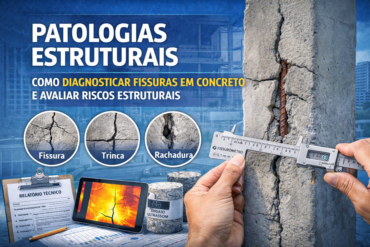















Cracks in concrete structures represent the most frequent and, at the same time, most concerning pathological manifestations in the Brazilian construction industry. Currently, studies indicate that between 70% and 80% of buildings older than 10 years exhibit some type of visible cracking. For this reason, understanding their causes, classifications, and diagnostic methods becomes fundamental to avoid structural collapses and significant financial losses.
Furthermore, although approximately 60% of the fissures are stable and treatable with simple interventions, about 40% can evolve into structurally critical cracks or fractures when not diagnosed correctly. Therefore, proper technical diagnosis is the main factor that separates an aesthetic problem from a real structural risk.
This comprehensive technical guide presents the scientific classification criteria, structural and non-structural causes, cracking patterns, diagnostic methods, and finally, the professional evaluation protocol.
Technical Classification: Fissure, Crack, Split, and Rupture
The classification of linear pathologies follows well-defined dimensional and structural criteria, in accordance with current technical standards.
Dimensional Criteria according to ABNT NBR 15575
| Pathology | Opening (mm) | Features | Gravity |
|---|---|---|---|
| Crack | < 0.5 | Microscopic, hair-like“ | Low |
| Crack | 0,5 – 1,0 | Visible to the naked eye | Average |
| Crack | > 1.0 | Open and worrying | High |
| Rupture | > 5.0 | Structural compromise | Review |
The recommended measurement method uses analog or digital crack gauges with a minimum accuracy of 0.02 mm, ensuring reliable classification.
Classification by Temporal Evolution
In addition to the opening, the evolution over time is crucial for diagnosis.
Stable Cracks – approximately 80% of cases
These cracks maintain a virtually constant width for periods exceeding 12 months. Furthermore, they do not exhibit significant variation when subjected to normal loads.
In this scenario, treatment is usually cosmetic or for superficial protection.
Active or Progressive Fissures – approximately 201% of cases
On the other hand, active cracks exhibit growth equal to or greater than 0.1 mm per year. They generally develop with loading, vibration, or environmental variation.
In these situations, structural intervention becomes urgent.
Cracking Patterns: The Map Reveals the Cause
In most cases, visual diagnosis accounts for approximately 70% of identifying the cause. Each fissure pattern indicates a specific mechanism.
1. Vertical Cracks in Pillars – approximately 40% of cases
These cracks are predominantly associated with differential settlement, concrete defects, or insufficient reinforcement. As a result, their severity ranges from moderate to high, requiring continuous monitoring.
2. Horizontal Cracks in Beams – approximately 25%
In this case, the most common causes involve excessive bending, carbonation of the concrete, and shrinkage due to variations in humidity and temperature. Although many are treatable, the progression should be monitored closely.
3. Diagonal Cracks in Columns or Beams – approximately 20%
This pattern represents an important warning. It typically indicates shear stress or angular settlement.
Therefore, this is a situation of high severity to critical, requiring immediate investigation.
4. Cracks in Map – approximately 15%
Map cracks are usually associated with generalized overload, thermal expansion with deformation restriction, or chemical reactions, such as the alkali-aggregate reaction.
Structural versus Non-Structural Causes
Structural Causes – predominant in severe cases
Among the structural causes, overloading beyond the designed load is a frequent occurrence. When the actual load significantly exceeds the design load, bending or compression cracks appear.
Furthermore, differential settlement between supports causes diagonal and angular cracks, especially in columns. Another recurring cause involves dimensional variations during construction, such as reduced sections compared to the design, leading to premature shear failures.
Non-structural causes – usually treatable
On the other hand, non-structural cracks include plastic shrinkage immediately after concreting, shrinkage due to drying over time, and thermal variations. Although they affect the visual appearance, these cracks rarely compromise structural safety when properly treated.
Five-Step Professional Diagnostic Protocol
Step 1: Structural History
Initially, a complete history of the building is collected, including the original design, construction records, renovations carried out, building maintenance, and extraordinary events.
Step 2: Systematic Visual Inspection
Next, a detailed inspection is carried out with photographic documentation and mapping of the cracks. This process utilizes a crack gauge, high-resolution camera, millimeter ruler, laser measuring tape and, when necessary, thermography.
Step 3: Non-Destructive Testing
Subsequently, non-destructive tests are applied to further the diagnosis. Among these, sclerometry, ultrasound, pacometry, carbonation testing, and thermography stand out.
An integrated interpretation of these results is essential. Often, the concrete has adequate strength, but the reinforcement is poorly positioned or has insufficient cover.
Step 4: Temporal Monitoring
When there are signs of activity, monitoring over 30 to 90 days becomes essential. The variation in the opening over time determines whether the crack is stable or active.
Step 5: Technical Report with Prognosis
Finally, a complete technical report is prepared, containing history, photographic mapping, test results, individual crack diagnosis, prognosis and intervention recommendations, as well as a preliminary budget.
Methods of Precise Measurement
The accuracy of the measurement directly influences the diagnosis.
| Method | Precision | Cost | Advantage |
|---|---|---|---|
| Analog fissure gauge | 0.1 mm | R$ 150 | Simplicity |
| Digital crack gauge | 0.02 mm | R$ 2.500 | High precision |
| 3D Scanner | 0.01 mm | R$ 50,000 | Complete mapping |
Furthermore, the standard establishes that the largest opening measured along the crack defines its classification.
Differential Diagnosis: When to Worry
Cracks less than 0.3 mm wide, stable and without exposed reinforcement, generally require only cosmetic treatment. In contrast, cracks between 0.3 and 0.7 mm or with a diagonal pattern require detailed investigation.
Cracks larger than 0.7 mm, active, with exposed reinforcement or visible settlement, constitute a critical situation and require immediate intervention.
Professional Tools and Equipment
A basic diagnostic kit includes a digital crack gauge, pachometer, thermal imager, and measuring instruments. In addition, software such as AutoCAD, Revit with Dynamo, and time series spreadsheets assist in technical control and documentation.
Conclusion: Correct Diagnosis Guarantees a Longer Lifespan
Correctly diagnosed cracks can prevent up to 90% of preventable structural collapses. Thus, a relatively small investment in technical diagnosis can avoid losses hundreds of times greater due to delayed repairs.
In summary, each cracking pattern reveals a specific cause. Skilled professionals can identify most origins through visual analysis alone, provided it is supported by technical methodology and reliable data.